In the previous tutorial, we introduced the sBPF memory layout and explained the purpose of each register during program execution.
In this tutorial, we’ll demonstrate how to read instruction input fields like account keys, program ID, and instruction data using sBPF assembly. In doing so, we’ll observe how they are laid out in memory.
Writing Assembly to read data from sBPF memory
When a Solana program runs, the runtime serializes the program’s instruction inputs (accounts, instruction data, program ID) and loads them into the input memory region starting at 0x400000000.
We’ll write simple assembly programs that read data from this input memory region into registers.
Setup
Create a new folder named assembly-experiment. Open a terminal in this folder and run solana-test-validator. This starts a local Solana cluster and creates a test-ledger directory to store ledger data.
Create the following folders and files in the assembly-experiment directory:
- A
srcfolder to hold your assembly program and trace output - A
src/inputs.asmfile for your assembly code - A
src/instructions.jsonfile for the transaction data that gets serialized and sent to the program
After creating the folder and files, the assembly-experiment folder should look like this:
assembly-experiment/
├── test-ledger/
└── src/
├── inputs.asm
└── instructions.json
Instruction serialization layout reference diagram
Remember the instruction serialization diagram from the previous tutorial? It maps the byte offset for each serialized field in memory. We’ll use these offsets to read specific data from the input region in our assembly code.

Using the ldxdw instruction to load data from memory into registers
In our assembly program, we’ll use the sBPF instruction ldxdw to load data from memory. This instruction performs an indexed load, where the final address is computed from a base register plus an offset.
This is what each part of the instruction means:
ldxmeans load from memory using a register plus an offset to calculate the address (indexed load). For example:[r1 + offset]. Theoffsetvariable will be replaced by the offset of the specific field within the serialized input.dwmeans the width of the load is a double-word, which is 64 bits or 8 bytes.
Each experiment must use an assembly program structured like the code below to load a value from memory into a register. The registers used in this example are arbitrary; any register would work. We use r1 here because it contains the instruction input at entry, while r2 has no special meaning and is used only for demonstration.
ldxdw r2, [r1 + offset]
exit
This program loads 8 bytes from memory address [r1 + offset] into register r2, then exits. Register r1 points to the start of the serialized instruction input at 0x400000000. We’ll replace offset with the actual byte offset of whichever field in memory we’re reading.
To see how the ldxdw instruction loads values from memory, consider this part of the instruction input serialization layout shown below:
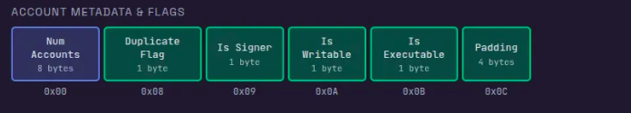
In this layout, the account count (Num Accounts) starts at offset 0x00, and the duplicate flag starts at offset 0x08. To load each value, replace offset with the field’s byte offset, and the VM reads from that location relative to the input base stored in r1.
Unlike the EVM where instruction inputs are accessed from calldata, Solana loads the instruction inputs into memory before execution begins. Here’s how this works in practice:
- To read the account count, use offset
0x00and load it from memory intor2withldxdw r2, [r1 + 0x00]. This reads from address0x400000000(0x400000000 + 0). If the instruction contains two accounts,r2will contain2. - To read the duplicate flag, use offset
0x08and load it withldxdw r2, [r1 + 0x08]. This reads from address0x400000008(0x400000000 + 8), which is where the flag field begins.
Throughout this article, we’ll use different offset values to inspect various parts of the memory region where the runtime stored the serialized instruction inputs.
Now that we’ve laid the foundation for understanding how to read from memory using the ldxdw instruction, let’s create our test data.
Setting up test input
We’ll create a test transaction instruction with a single account in the accounts array, owned by the BPF Loader. This will allow us to illustrate how the VM reads the serialized instruction input.
The test data below includes:
- An accounts array with the following format:
- public key
- owner
- Account flags: not a signer, writable, not executable
- 1,000 lamports balance
- 4 bytes of account data:
[0, 0, 0, 3]
- A program ID
- 4 bytes of instruction data:
[2, 0, 0, 0]
Here is the test data, paste it into src/instructions.json. The runtime will use this to load the instruction into memory. Throughout this tutorial, we’ll examine how the sBPF VM reads the instruction from memory.
{
"accounts": [
{
"key": "524HMdYYBy6TAn4dK5vCcjiTmT2sxV6Xoue5EXrz22Ca",
"owner": "BPFLoaderUpgradeab1e11111111111111111111111",
"is_signer": false,
"is_writable": true,
"lamports": 1000,
"data": [0, 0, 0, 3]
}
],
"program_id": "HTpqQdG7f44su3QsV3HHurraR1ZNjHAdArCy3qHKyKBC",
"instruction_data": [2, 0, 0, 0]
}
Below is a quick reminder of how to run the agave-ledger-tool.
Running our assembly code
We’ll use agave-ledger-tool to run our assembly code and trace register states after each instruction. This tool comes pre-installed with your Solana development installation.
The agave-ledger-tool generates execution traces showing register state transitions. Since we cannot directly view memory contents, we’ll copy values from memory into registers and inspect those registers in the trace output.
Below is the agave-ledger-tool command we’ll use to execute our assembly programs. It will execute our program with a 200,000 compute unit limit, write a trace file showing register states, uses our local test ledger, and takes input from our instructions.json file:
agave-ledger-tool program run inputs/inputs.asm --limit 200000 --trace inputs/trace.txt --ledger test-ledger --input inputs/instructions.json
Reading the account count in our test input
According to the serialization format diagram we showed earlier, the first 8 bytes contain the number of accounts with an offset of 0x00. Our input parameter contains only one account in the accounts list:
{
"accounts": [
{
"key": "524HMdYYBy6TAn4dK5vCcjiTmT2sxV6Xoue5EXrz22Ca",
"owner": "BPFLoaderUpgradeab1e11111111111111111111111",
"is_signer": false,
"is_writable": true,
"lamports": 1000,
"data": [0, 0, 0, 3]
}
],
... // other input parameters
}
To demonstrate this, replace offset with 0x00 in your assembly program. This loads 8 bytes from address r1 + 0x00 (that is, 0x400000000) into r2. The choice of r2 is arbitrary, any other argument register could be used here.
ldxdw r2, [r1 + 0x00]
exit
Run the program using the agave-ledger-tool command, then open inputs/trace.txt to see the execution trace:
Frame 0
0 [0000000000000000, 0000000400000000, 0000000000000000, 0000000000000000, 0000000000000000, 0000000000000000, 0000000000000000, 0000000000000000, 0000000000000000, 0000000000000000, 0000000200001000] 0: ldxdw r2, [r1+0x0]
1 [0000000000000000, 0000000400000000, 0000000000000001, 0000000000000000, 0000000000000000, 0000000000000000, 0000000000000000, 0000000000000000, 0000000000000000, 0000000000000000, 0000000200001000] 1: exit
The trace shows register states before and after each instruction. The array displays registers in order: [r0, r1, r2, r3, r4, r5, r6, r7, r8, r9, r10].
Line 0 shows initial state: r1 holds 0x400000000 (the input base address) and r2 is zero.
Line 1 shows the state after the ldxdw r2, [r1+0x0] instruction execution: r2 now contains 1 (0000000000000001), which is the number of accounts in our transaction input.
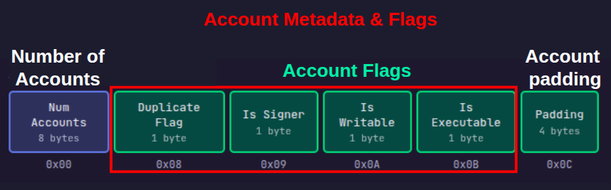
Reading account flags and padding region
The next 8 bytes, starting at offset 0x08, contain 4 one-byte flags followed by 4 bytes of padding as shown in the diagram below. Since registers hold 8 bytes, we’ll load all the flags and padding at once into a register.
The duplicate flag is a single byte at offset 0x08 with the following properties:
- if the account is unique, the duplicate flag will be
0xFFbyte. - if the account is a duplicate of an earlier account in the accounts array, the duplicate flag should be the index of the original account.
Our test transaction data only has one account, so it cannot be a duplicate.
We can see the content of these flags in memory by loading them into registers using the ldxdw r2, [r1 + offset] instruction. Replacing the offset variable with the offset we intend to start reading from.
Let’s show that the duplicate flag has the value 0xFF (indicating a unique account):
ldxdw r2, [r1 + 0x08]
exit
Remember that ldxdw loads 8 bytes, not just 1 byte. So even though the duplicate flag is only the first byte at offset 0x08, this instruction will load the duplicate flag plus the 7 bytes that follow it into r2. This means we’ll also see the other account flags and padding that occupy offsets 0x08 through 0x0F.
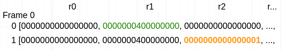
Run the program and check src/trace.txt:
Frame 0
0 [0000000000000000, 0000000400000000, 0000000000000000, 0000000000000000, 0000000000000000, 0000000000000000, 0000000000000000, 0000000000000000, 0000000000000000, 0000000000000000, 0000000200001000] 0: ldxdw r2, [r1+0x8]
1 [0000000000000000, 0000000400000000, **00000000000100FF**, 0000000000000000, 0000000000000000, 0000000000000000, 0000000000000000, 0000000000000000, 0000000000000000, 0000000000000000, 0000000200001000] 1: exit
The trace shows that register r2 now contains 00000000000100FF (In little-endian format—the rightmost byte FF is at the lowest memory address 0x08), hence we will read the highlighted bytes in reverse, which means:
FF(byte 0, offset0x08): duplicate flag,0xFFmeans it’s not a duplicate00(byte 1, offset0x09): account is not a signer. In our transaction, we set this tofalsewhich translates to001(byte 2, offset0x0A): account is writable. In our transaction, we set this totruewhich translates to100(byte 3, offset0x0B): account is not executable. We did not set this, it defaults tofalse00000000(bytes 4-7, offsets0x0C-0x0F): account padding
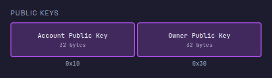
Reading the account public key
The next 32 bytes of the serialized instruction input contain the account’s public key, followed by another 32 bytes for the owner’s public key (discussed in the next section).
A register holds 8 bytes. Since we are trying to load more than 8 bytes, we have to use multiple registers. We’ll load the account public key in four chunks across registers r2, r3, r4, and r5.
The program below loads four 8-byte chunks from memory into registers. Replace the contents of src/inputs.asm with the following code:
ldxdw r2, [r1+16] ; Load bytes 16-23 (first 8 bytes of public key) into r2
ldxdw r3, [r1+24] ; Load bytes 24-31 (next 8 bytes) into r3
ldxdw r4, [r1+32] ; Load bytes 32-39 (next 8 bytes) into r4
ldxdw r5, [r1+40] ; Load bytes 40-47 (last 8 bytes) into r5
exit
Run the program with the agave-ledger-tool. The trace file should now have this content:
Frame 0
0 [0000000000000000, 0000000400000000, 0000000000000000, 0000000000000000, 0000000000000000, 0000000000000000, 0000000000000000, 0000000000000000, 0000000000000000, 0000000000000000, 0000000200001000] 0: ldxdw r2, [r1+0x10]
1 [0000000000000000, 0000000400000000, FA44AE351B0AB43B, 0000000000000000, 0000000000000000, 0000000000000000, 0000000000000000, 0000000000000000, 0000000000000000, 0000000000000000, 0000000200001000] 1: ldxdw r3, [r1+0x18]
2 [0000000000000000, 0000000400000000, FA44AE351B0AB43B, 82F50D147D40C5B6, 0000000000000000, 0000000000000000, 0000000000000000, 0000000000000000, 0000000000000000, 0000000000000000, 0000000200001000] 2: ldxdw r4, [r1+0x20]
3 [0000000000000000, 0000000400000000, FA44AE351B0AB43B, 82F50D147D40C5B6, 35145241BD93D13F, 0000000000000000, 0000000000000000, 0000000000000000, 0000000000000000, 0000000000000000, 0000000200001000] 3: ldxdw r5, [r1+0x28]
4 [0000000000000000, 0000000400000000, FA44AE351B0AB43B, 82F50D147D40C5B6, 35145241BD93D13F, 1B20575E7D084725, 0000000000000000, 0000000000000000, 0000000000000000, 0000000000000000, 0000000200001000] 4: exit
Remember the string below is the public key we have in the instructions.json file that’s being stored in memory and loaded into registers.
524HMdYYBy6TAn4dK5vCcjiTmT2sxV6Xoue5EXrz22Ca
If we convert the public key from it’s original base58 format to hex, we’ll have this:
3BB40A1B35AE44FAB6C5407D140DF5823FD193BD415214352547087D5E57201B
We’ll split it into 8-bytes for each register since that’s what each register can store. We’ll have this:
0x3bb40a1b35ae44fa 0xb6c5407d140df582 0x3fd193bd41521435 0x2547087d5e57201b
Register values are displayed/interpreted in little-endian order, so the 8-byte chunks appear as shown below.
FA44AE351B0AB43B 82F50D147D40C5B6 35145241BD93D13F 1B20575E7D084725
Let’s trace through each step:
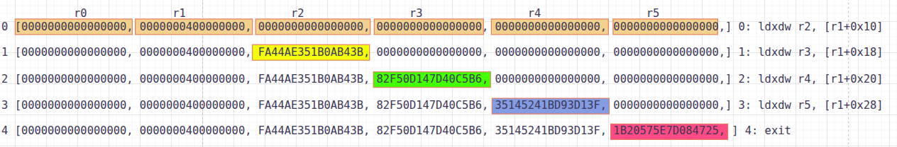
- Line 0: Initial state before any loads. All registers (
r0-r10) are shown, withr1containing0000000400000000(MM_INPUT_START). - Line 1: After executing
ldxdw r2, [r1+16], registerr2(third position) now containsFA44AE351B0AB43B(the first 8 bytes of the public key in little-endian format). - Line 2: After executing
ldxdw r3, [r1+24], registerr3(fourth position) now contains82F50D147D40C5B6(the next 8 bytes). - Line 3: After executing
ldxdw r4, [r1+32], registerr4(fifth position) now contains35145241BD93D13F(the next 8 bytes). - Line 4: After executing
ldxdw r5, [r1+40], registerr5(sixth position) now contains1B20575E7D084725(the last 8 bytes).
Comparing each register (r2, r3, r4, r5) to our expected hex values shows they match perfectly.
Reading the owner public key
The owner public key starts at offset 0x30 (48 decimal) after the account public key and spans 32 bytes. Since each ldxdw instruction loads 8 bytes, you need four loads to read the entire key. The owner in our example is BPFLoaderUpgradeab1e11111111111111111111111
Let’s demonstrate that with the code below. Update src/inputs.asm:
ldxdw r2, [r1+48] ; Load bytes 48-55 (first 8 bytes of owner public key) into r2
ldxdw r3, [r1+56] ; Load bytes 56-63 (next 8 bytes) into r3
ldxdw r4, [r1+64] ; Load bytes 64-71 (next 8 bytes) into r4
ldxdw r5, [r1+72] ; Load bytes 72-79 (last 8 bytes) into r5
exit
Run the code. The trace shows each register loading its 8-byte chunk:
Frame 0
0 [0000000000000000, 0000000400000000, 0000000000000000, 0000000000000000, 0000000000000000, 0000000000000000, 0000000000000000, 0000000000000000, 0000000000000000, 0000000000000000, 0000000200001000] 0: ldxdw r2, [r1+0x30]
1 [0000000000000000, 0000000400000000, B0A1884E91F6A802, 0000000000000000, 0000000000000000, 0000000000000000, 0000000000000000, 0000000000000000, 0000000000000000, 0000000000000000, 0000000200001000] 1: ldxdw r3, [r1+0x38]
2 [0000000000000000, 0000000400000000, B0A1884E91F6A802, 2BAE63F73E1510E2, 0000000000000000, 0000000000000000, 0000000000000000, 0000000000000000, 0000000000000000, 0000000000000000, 0000000200001000] 2: ldxdw r4, [r1+0x40]
3 [0000000000000000, 0000000400000000, B0A1884E91F6A802, 2BAE63F73E1510E2, D224C1163DB9C200, 0000000000000000, 0000000000000000, 0000000000000000, 0000000000000000, 0000000000000000, 0000000200001000] 3: ldxdw r5, [r1+0x48]
4 [0000000000000000, 0000000400000000, B0A1884E91F6A802, 2BAE63F73E1510E2, D224C1163DB9C200, 00008004107A53C0, 0000000000000000, 0000000000000000, 0000000000000000, 0000000000000000, 0000000200001000] 4: exit
When you convert the owner address BPFLoaderUpgradeab1e11111111111111111111111 to hex and split it into 8-byte little-endian chunks, you get:
B0A1884E91F6A802 2BAE63F73E1510E2 D224C1163DB9C200 00008004107A53C0
These values match what appears in registers r2 through r5 in the trace.
Reading lamports
The next 8 bytes after the owner public key contain the account’s lamport balance. The lamports field is located at offset 0x50 (80 in decimal) in memory.
Let’s load the lamports field into a register and inspect it. Use 0x50 as the offset in our assembly program:
ldxdw r2, [r1 + 0x50]
exit
Run the program and check src/trace.txt:
Frame 0
0 [0000000000000000, 0000000400000000, 0000000000000000, 0000000000000000, 0000000000000000, 0000000000000000, 0000000000000000, 0000000000000000, 0000000000000000, 0000000000000000, 0000000200001000] 0: ldxdw r2, [r1+0x50]
1 [0000000000000000, 0000000400000000, **00000000000003E8**, 0000000000000000, 0000000000000000, 0000000000000000, 0000000000000000, 0000000000000000, 0000000000000000, 0000000000000000, 0000000200001000] 1: exit
We see that Register r2 holds 00000000000003E8, which is the hex representation of 1,000 lamports. This matches the lamports: 1000 value in our instructions file.
Reading account data length
The next 8 bytes after the lamports field is the length of the account data, located at offset 0x58. Update src/inputs.asm to read from offset 0x58:
ldxdw r2, [r1 + 0x58]
exit
Run the program and check src/trace.txt:
Frame 0
0 [0000000000000000, 0000000400000000, 0000000000000000, 0000000000000000, 0000000000000000, 0000000000000000, 0000000000000000, 0000000000000000, 0000000000000000, 0000000000000000, 0000000200001000] 0: ldxdw r2, [r1+0x58]
1 [0000000000000000, 0000000400000000, **0000000000000004**, 0000000000000000, 0000000000000000, 0000000000000000, 0000000000000000, 0000000000000000, 0000000000000000, 0000000000000000, 0000000200001000] 1: exit
Register r2 contains 0000000000000004, indicating our account has 4 bytes of data. This matches the 4-element array in the data: [0, 0, 0, 3] field of our instructions.json file.
Reading account data
The account data starts at offset 0x60, immediately after the account data length. Our test account has 4 bytes of data spanning offsets 0x60-0x63. To show this, let’s load the data at offset 0x60:
ldxdw r2, [r1 + 0x60]
exit
Run the program. The trace shows:
Frame 0
0 [0000000000000000, 0000000400000000, 0000000000000000, 0000000000000000, 0000000000000000, 0000000000000000, 0000000000000000, 0000000000000000, 0000000000000000, 0000000000000000, 0000000200001000] 0: ldxdw r2, [r1+0x60]
1 [0000000000000000, 0000000400000000, **0000000003000000**, 0000000000000000, 0000000000000000, 0000000000000000, 0000000000000000, 0000000000000000, 0000000000000000, 0000000000000000, 0000000200001000] 1: exit
Register r2 contains 0000000003000000. The instruction loads 8 bytes, but only the first 4 bytes contain your actual data. Reading those 4 bytes right to left (little-endian) gives [00, 00, 00, 03], matching data: [0, 0, 0, 3] from the instruction file.
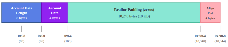
Reading realloc padding
After the account data, the runtime reserves 10,240 bytes (10 KiB) of zero-filled space for potential account data growth during program execution (via reallocation).
This padding starts at offset 0x64 (where our 4-byte account data ends) and extends to offset 0x2864 (10,340 in decimal).
We can show this by loading a random offset within this range from memory into a register. Let’s check offset 0x1388:
ldxdw r2, [r1 + 0x1388]
exit
Run the program. Register r2 should contain 0000000000000000, showing that this region is filled with zeros.
Frame 0
0 [0000000000000000, 0000000400000000, 0000000000000000, 0000000000000000, 0000000000000000, 0000000000000000, 0000000000000000, 0000000000000000, 0000000000000000, 0000000000000000, 0000000200001000] 0: ldxdw r2, [r1+0x1388]
1 [0000000000000000, 0000000400000000, **0000000000000000**, 0000000000000000, 0000000000000000, 0000000000000000, 0000000000000000, 0000000000000000, 0000000000000000, 0000000000000000, 0000000200001000] 1: exit
Reading alignment padding
After the 10k realloc padding, the next field must start on an 8-byte boundary. The realloc padding ends at offset 0x2864 (10340). Because this offset is not 8-byte aligned, the runtime rounds it up to 10344, adding 4 bytes of alignment padding.
To examine the memory contents at the boundary between the realloc padding and the next field, let’s load from offset 0x2864 into r2 and inspect the trace.
ldxdw r2, [r1 + 0x2864]
exit
The trace should show FFFFFFFF00000000 in register r2:
Frame 0
0 [0000000000000000, 0000000400000000, 0000000000000000, 0000000000000000, 0000000000000000, 0000000000000000, 0000000000000000, 0000000000000000, 0000000000000000, 0000000000000000, 0000000200001000] 0: ldxdw r2, [r1+0x2864]
1 [0000000000000000, 0000000400000000, FFFFFFFF00000000, 0000000000000000, 0000000000000000, 0000000000000000, 0000000000000000, 0000000000000000, 0000000000000000, 0000000000000000, 0000000200001000] 1: exit
FFFFFFFF00000000 in little-endian form corresponds to the bytes 00 00 00 00 FF FF FF FF. Our ldxdw instruction reads across two fields: the first four zero bytes are the alignment padding, and the next four FF bytes are the beginning of the rent epoch field. Which we’ll discuss next.
Reading rent epoch
The next 8 bytes after the alignment padding contain the rent epoch for the account.
In practice, accounts in Solana are created rent-exempt, so the rent epoch field is set to the default rent-exempt value encoded as FFFFFFFFFFFFFFFF.
To show this, we’ll load the rent epoch from offset 10344 (0x2868), which is the start of the rent epoch region into r2.
ldxdw r2, [r1 + 0x2868]
exit
Running this should show:
Frame 0
0 [0000000000000000, 0000000400000000, 0000000000000000, 0000000000000000, 0000000000000000, 0000000000000000, 0000000000000000, 0000000000000000, 0000000000000000, 0000000000000000, 0000000200001000] 0: ldxdw r2, [r1+0x2868]
1 [0000000000000000, 0000000400000000, **FFFFFFFFFFFFFFFF**, 0000000000000000, 0000000000000000, 0000000000000000, 0000000000000000, 0000000000000000, 0000000000000000, 0000000000000000, 0000000200001000] 1: exit
Register r2 contains FFFFFFFFFFFFFFFF.
Reading instruction data length
The next 8 bytes after the rent epoch contain the length of the instruction data at offset 10352. Our test transaction includes 4 bytes of instruction data. Replace offset with 10352:
ldxdw r2, [r1 + 10352]
exit
The code should produce this trace when you run it:
Frame 0
0 [0000000000000000, 0000000400000000, 0000000000000000, 0000000000000000, 0000000000000000, 0000000000000000, 0000000000000000, 0000000000000000, 0000000000000000, 0000000000000000, 0000000200001000] 0: ldxdw r2, [r1+0x2870]
1 [0000000000000000, 0000000400000000, 0000000000000004, 0000000000000000, 0000000000000000, 0000000000000000, 0000000000000000, 0000000000000000, 0000000000000000, 0000000000000000, 0000000200001000] 1: exit
Register r2 contains 0000000000000004, which shows that the instruction data array has 4 bytes as specified in our instructions.json file.
Reading instruction data
The next bytes, starting at offset 10360, contain the instruction data. Our test includes 4 bytes: [2, 0, 0, 0], (but this length varies per transaction). Replace offset with 10360 (0x2878 in hex) to inspect it:
ldxdw r2, [r1 + 0x2878]
exit
The code produces this trace when you run it:
Frame 0
0 [0000000000000000, 0000000400000000, 0000000000000000, 0000000000000000, 0000000000000000, 0000000000000000, 0000000000000000, 0000000000000000, 0000000000000000, 0000000000000000, 0000000200001000] 0: ldxdw r2, [r1+0x2878]
1 [0000000000000000, 0000000400000000, **BA2D9AF400000002**, 0000000000000000, 0000000000000000, 0000000000000000, 0000000000000000, 0000000000000000, 0000000000000000, 0000000000000000, 0000000200001000] 1: exit
Register r2 contains BA2D9AF400000002. Since ldxdw loads 8 bytes but the instruction data is only 4 bytes long, this read also includes the first 4 bytes of the following field. The lower 32 bits (00000002) represent our instruction data [2, 0, 0, 0] in little-endian format.
Reading program ID
The final 32 bytes contain the program ID of the program being invoked. Since our instruction data is 4 bytes long, it occupies offsets 10360- 10363. The program ID begins immediately after at offset 10364 (0x287C in hex).
To inspect it, we can load all 32 bytes across four registers:
ldxdw r2, [r1+10364]
ldxdw r3, [r1+10372]
ldxdw r4, [r1+10380]
ldxdw r5, [r1+10388]
exit
Run the program and check the trace file:
Frame 0
0 [0000000000000000, 0000000400000000, 0000000000000000, 0000000000000000, 0000000000000000, 0000000000000000, 0000000000000000, 0000000000000000, 0000000000000000, 0000000000000000, 0000000200001000] 29: ldxdw r2, [r1+0x287c]
1 [0000000000000000, 0000000400000000, C512BA35BA2D9AF4, 0000000000000000, 0000000000000000, 0000000000000000, 0000000000000000, 0000000000000000, 0000000000000000, 0000000000000000, 0000000200001000] 30: ldxdw r3, [r1+0x2884]
2 [0000000000000000, 0000000400000000, C512BA35BA2D9AF4, 08D0A2FB506C1A71, 0000000000000000, 0000000000000000, 0000000000000000, 0000000000000000, 0000000000000000, 0000000000000000, 0000000200001000] 31: ldxdw r4, [r1+0x288c]
3 [0000000000000000, 0000000400000000, C512BA35BA2D9AF4, 08D0A2FB506C1A71, 93EAF43A2BD4867A, 0000000000000000, 0000000000000000, 0000000000000000, 0000000000000000, 0000000000000000, 0000000200001000] 32: ldxdw r5, [r1+0x2894]
4 [0000000000000000, 0000000400000000, C512BA35BA2D9AF4, 08D0A2FB506C1A71, 93EAF43A2BD4867A, B7CFB5A9E7B8C99A, 0000000000000000, 0000000000000000, 0000000000000000, 0000000000000000, 0000000200001000] 33: exit
The four registers contain the complete program ID in little-endian format. To reconstruct the program ID, we reverse the byte order of each register value and concatenate them:
- r2:
C512BA35BA2D9AF4→F49A2DBA35BA12C5 - r3:
08D0A2FB506C1A71→711A6C50FBA2D008 - r4:
93EAF43A2BD4867A→7A86D42B3AF4EA93 - r5:
B7CFB5A9E7B8C99A→9AC9B8E7A9B5CFB7
Concatenating these gives us 0xf49a2dba35ba12c5711a6c50fba2d0087a86d42b3af4ea939ac9b8e7a9b5cfb7 in hex, which decodes to HTpqQdG7f44su3QsV3HHurraR1ZNjHAdArCy3qHKyKBC in base58. This matches the program_id field in our instructions.json file.
Testing with empty accounts array or instruction data
When a transaction has an empty accounts array or no instruction data, the VM only reserves space for the count fields (account count and instruction data length), which will both be 0. We’ll demonstrate this with actual examples in the next article, where we discuss syscalls.
This article is part of a tutorial series on Solana development